You know when it says attach the freestanding units/bookshelfs etc to the wall and you never do it? Well now there’s little people about, it’s a necessity. Especially when theres a fan on top…
Not to sure how I contained my excitement as our almost £400 fan came tumbling down on top of our two year old. Thankfully, he was OK ish and the two year old also sustained no injuries.
Ok-ish, well not quite as the manual tilting feature, pivots from the bottom area, was not functioning as such. Having looked online for instructions to disassemble and failing, I proceeded to take apart. Luckily for this guide but not so lucky for me the whole thing had to come apart.
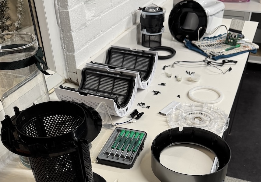
It’s relatively easy to take apart and I didn’t take pictures until I assembled it back together.
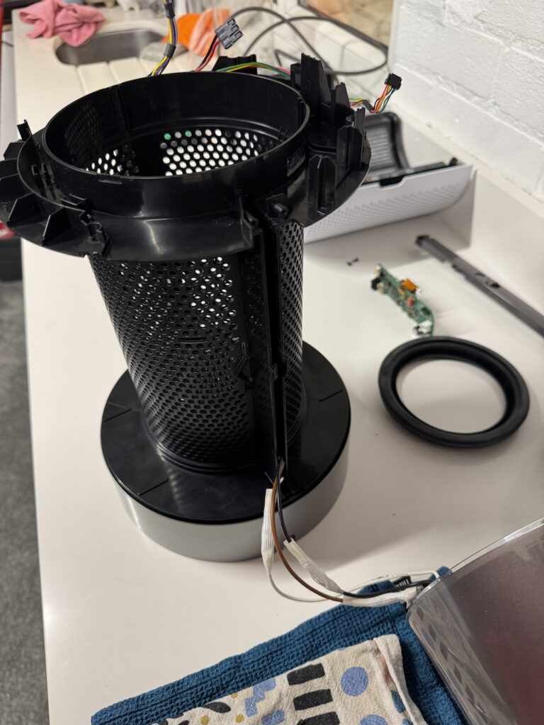
Here goes, How to assemble a A Dyson HP10 Fan fan from near enough in bits, top part / heater element housing not disassembled. And if you follow it in reverse, how to disassemble.
Note – If your rotation is not working, See Here
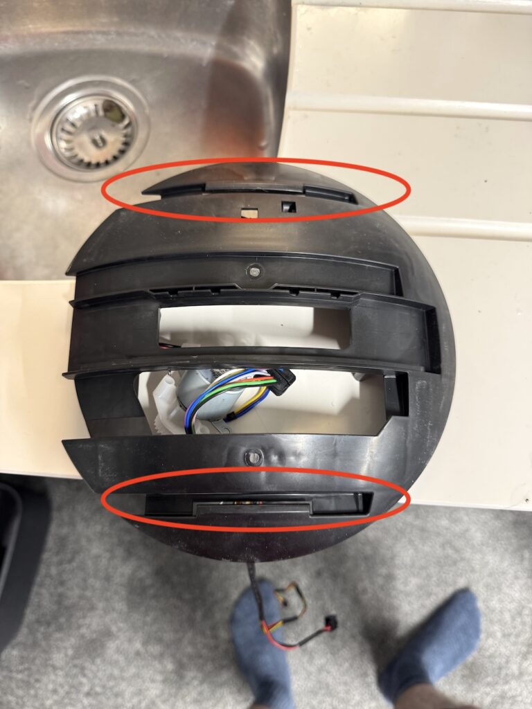
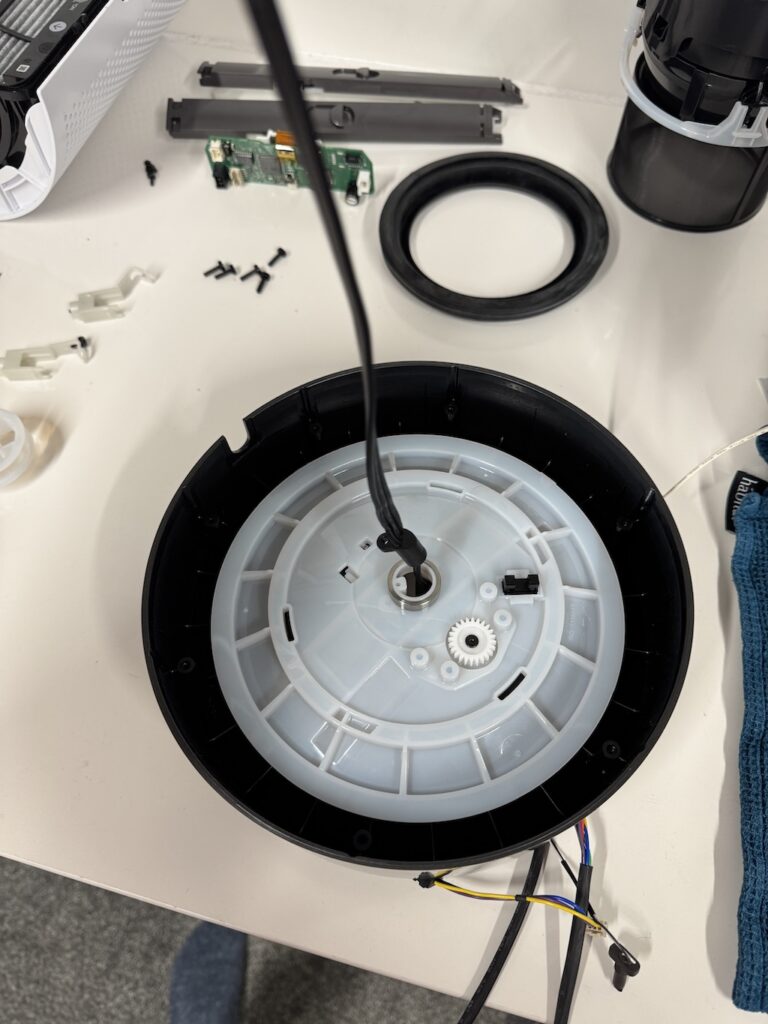
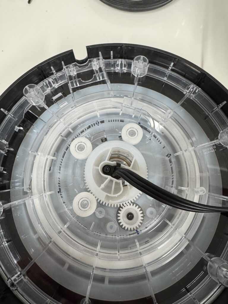
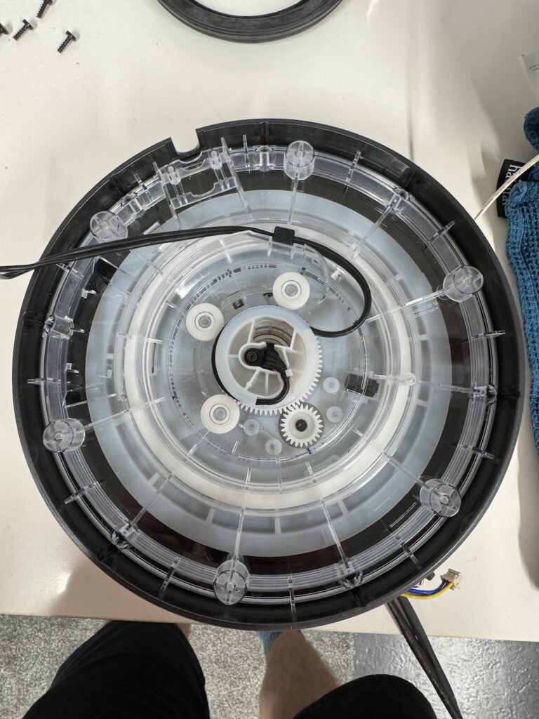
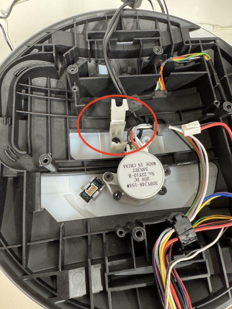
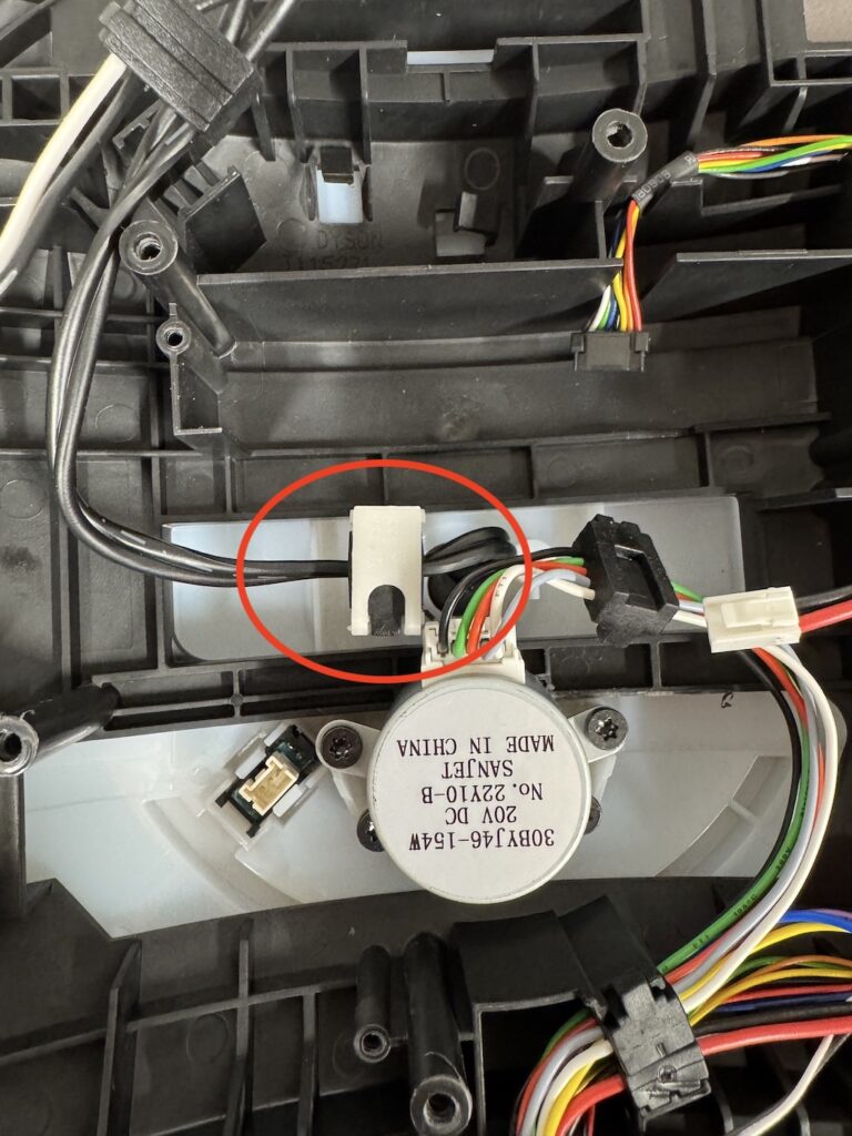
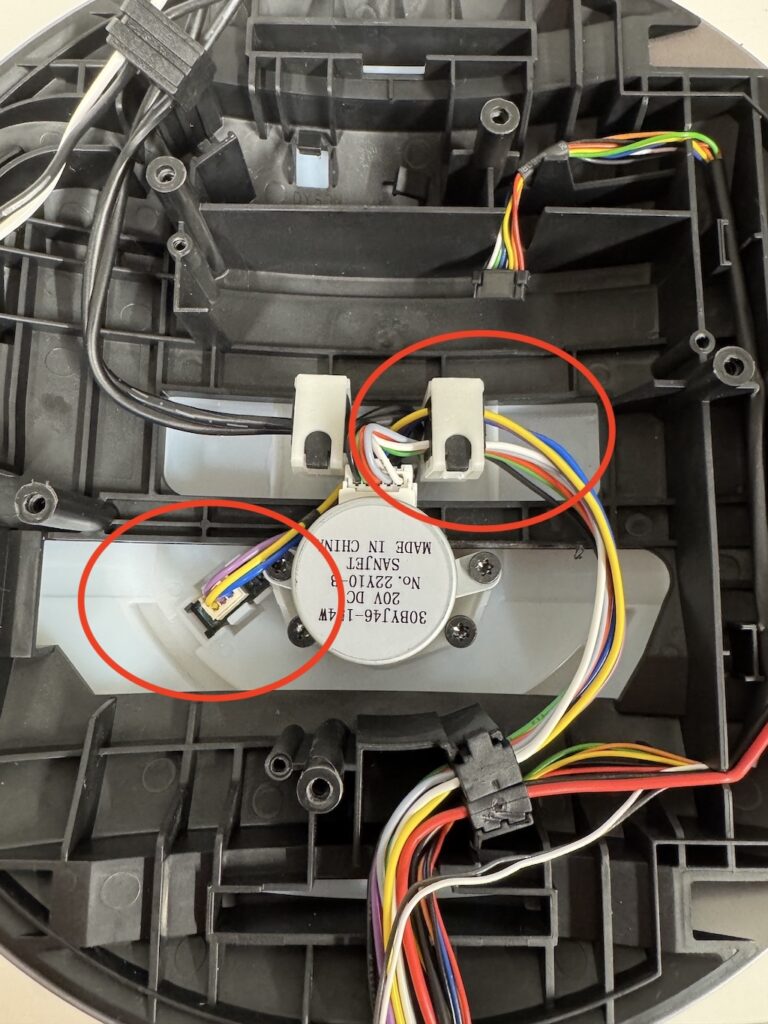
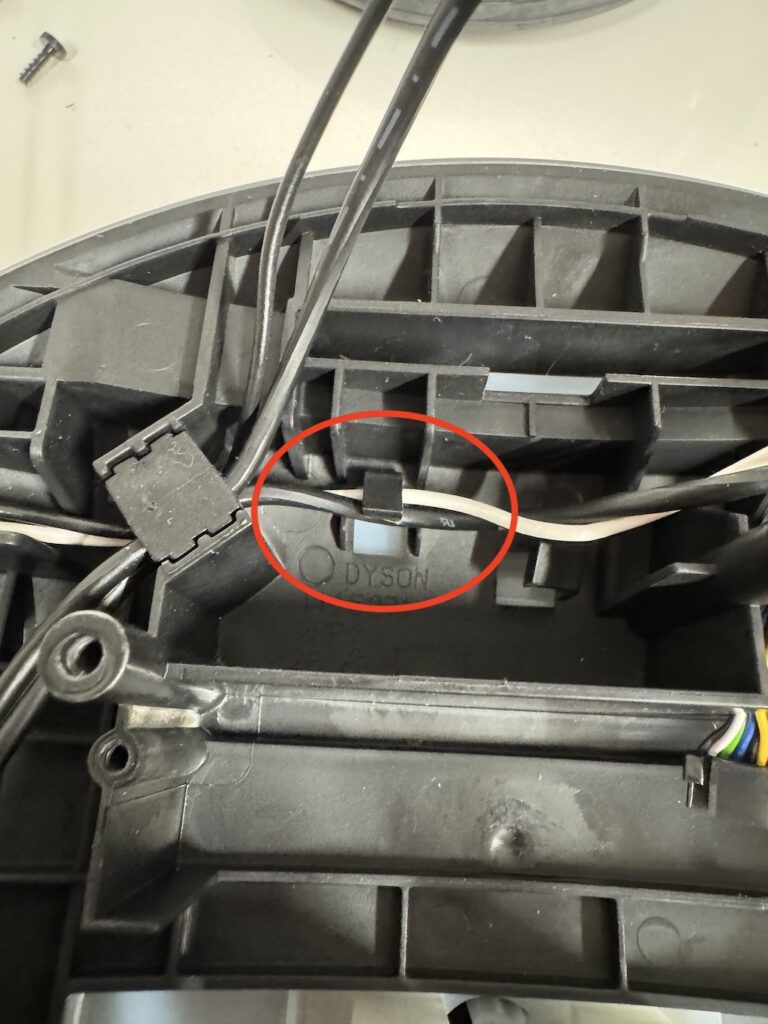
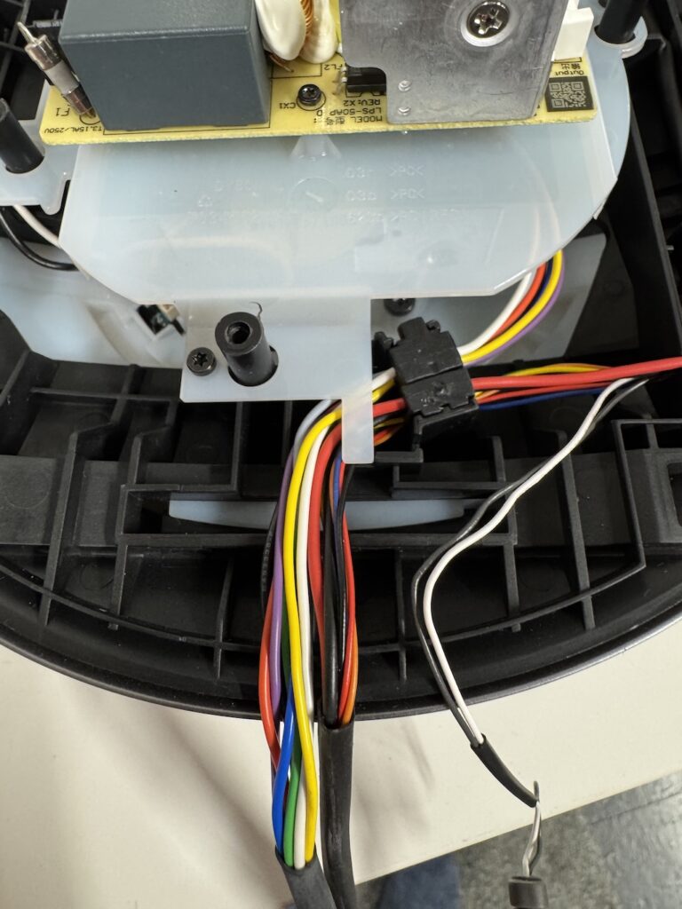
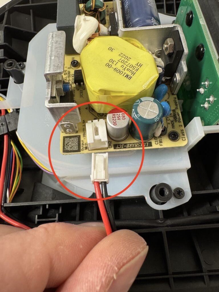
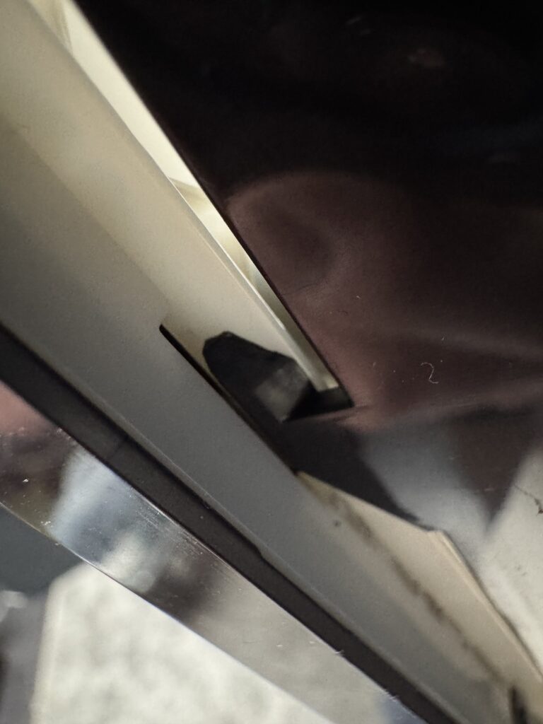
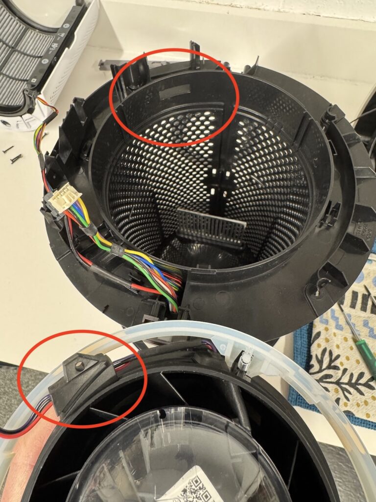
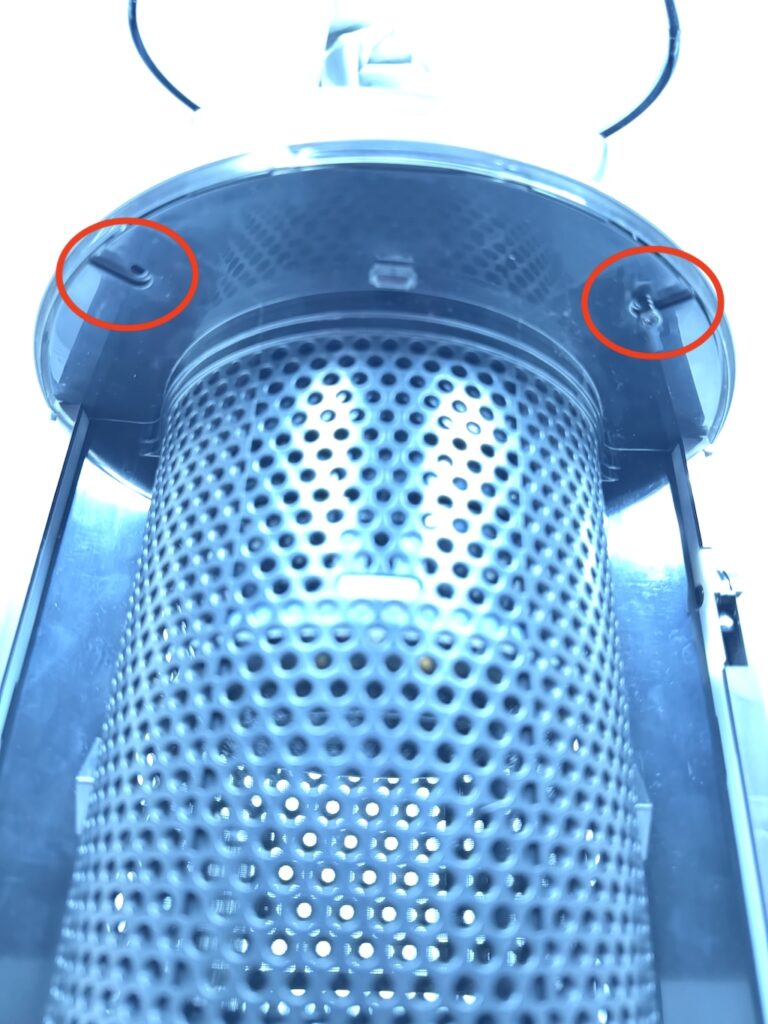
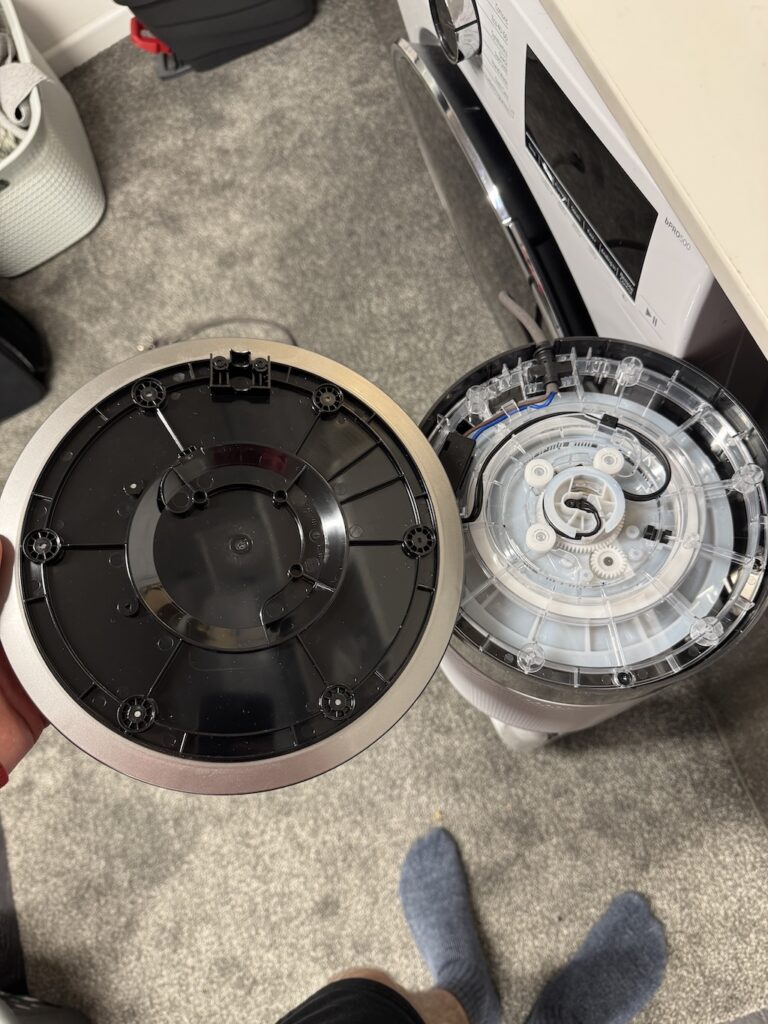
First off, the actual issue with mine was that these two parts, lets call the white part the rotation gear housing tray & the black part the lower components housing, had come apart from each other as it hit the deck. They sandwich the grey part and the red circled highlights show where the parts interlock.
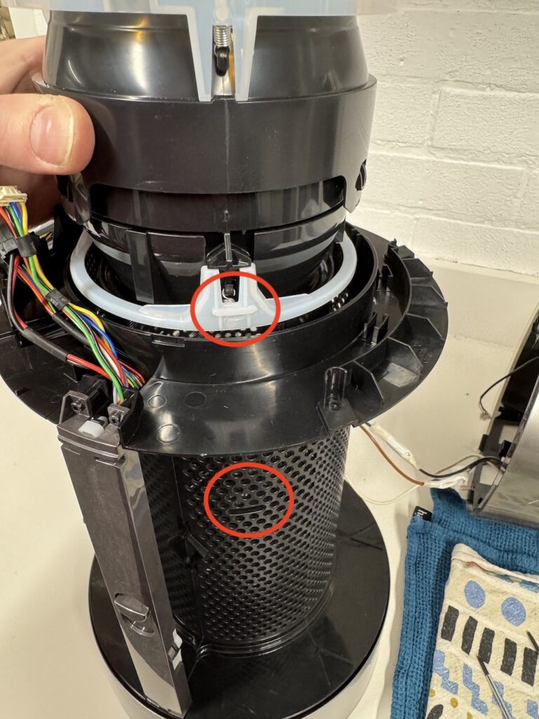
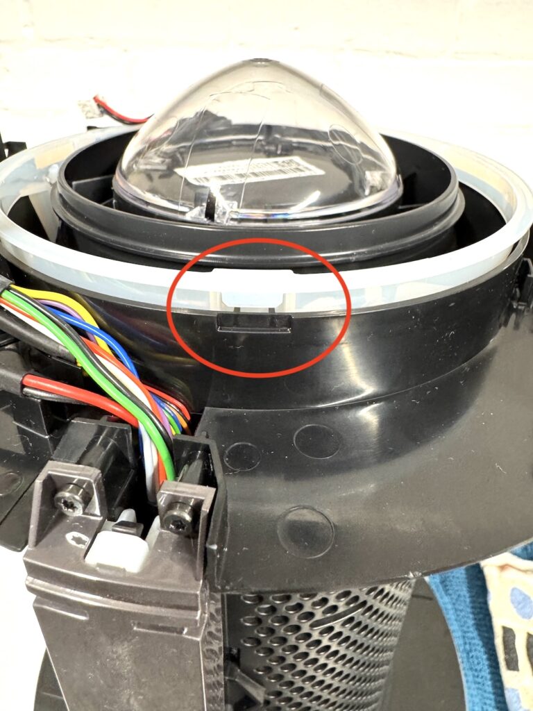
Note that the centre tilt lock is in position with the spring
Note that the rotation sensor is in situ in the middle picture.
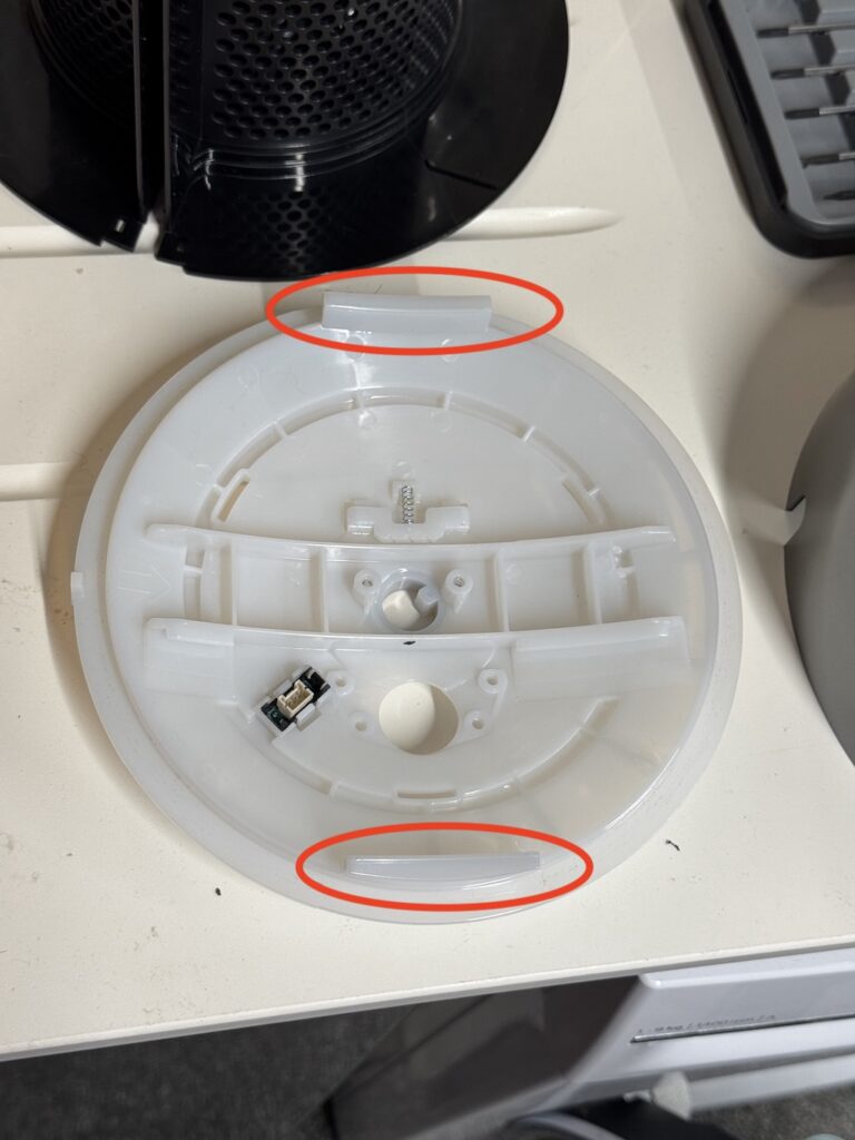
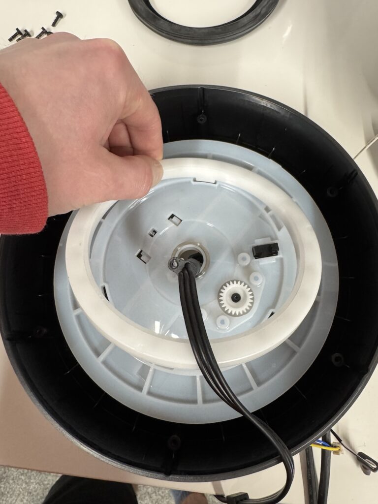
So gear housing on the bottom, put the grey circle part over the top and then slide the lower component housing into the gear housing. It will only go on one way.
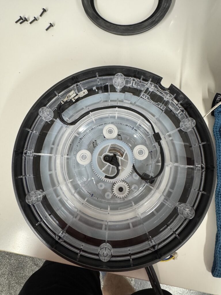
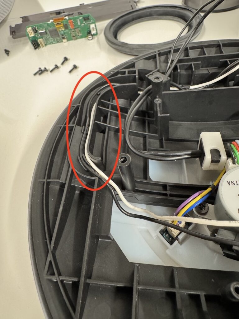
It can be a bit fiddly to get the guides to line up but there is a bit of flexibility in the plastic to manoeuvre it in and should look something like this, the wiring is in situ as it saved taking it completely out.
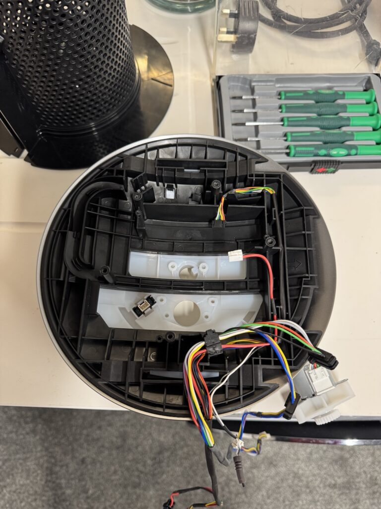
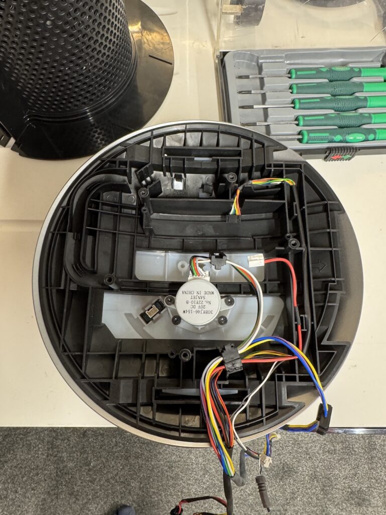
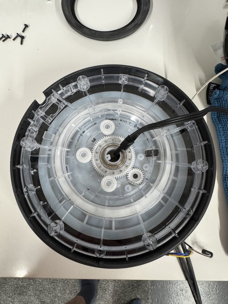
Pop in the rotation motor. 4 Screws holding in.
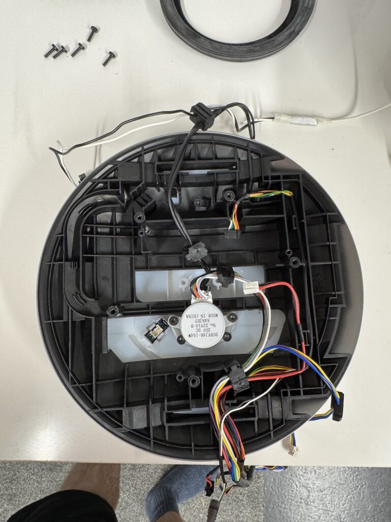
Flip this assembly over & feed through the main power cable from the inside to the outside.
Add the rotation bearing. Three locating tabs to sit in.
Add the power cable housing
Feed through the power cable securing / gear housing cap on the large opening. Slide it through to the centre and put the screw in.

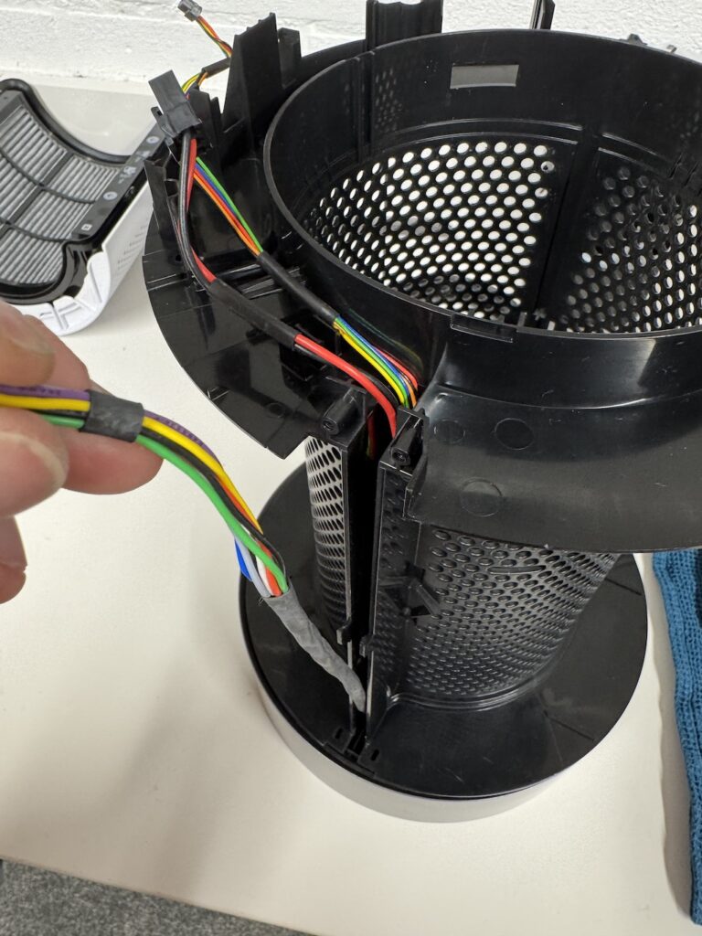
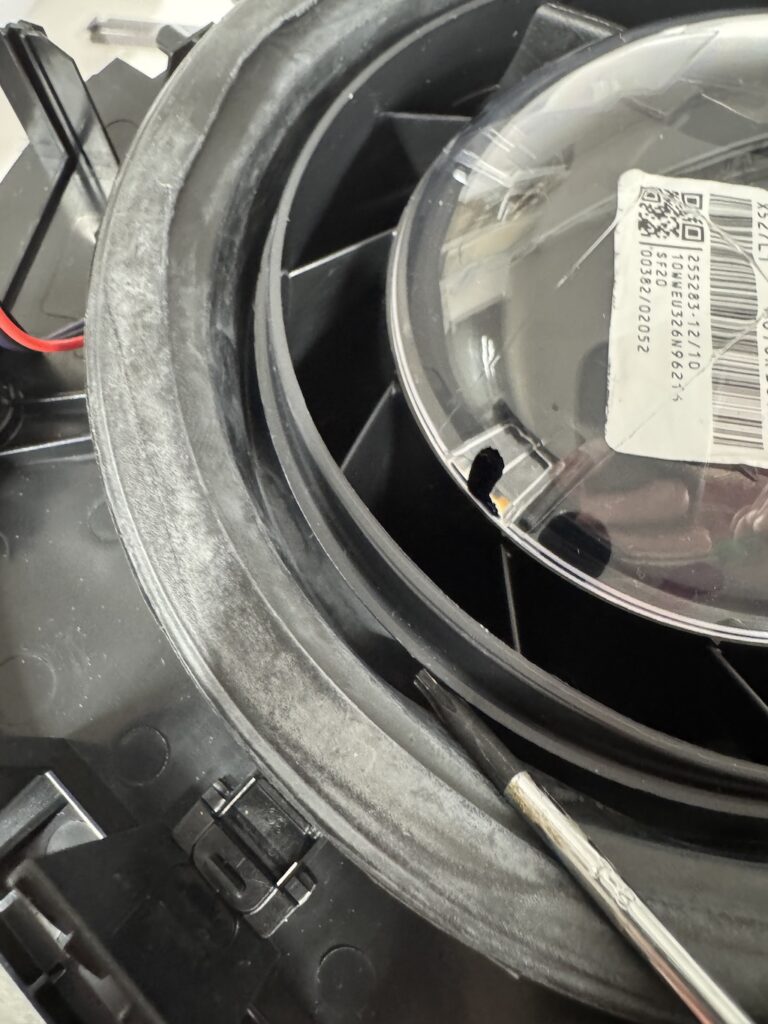
Feed the cable around the roller section and into the guide. For now, we will leave this with the two spade terminals tucked in place.
Next flip the unit back over, ensure the wiring is in the guides.
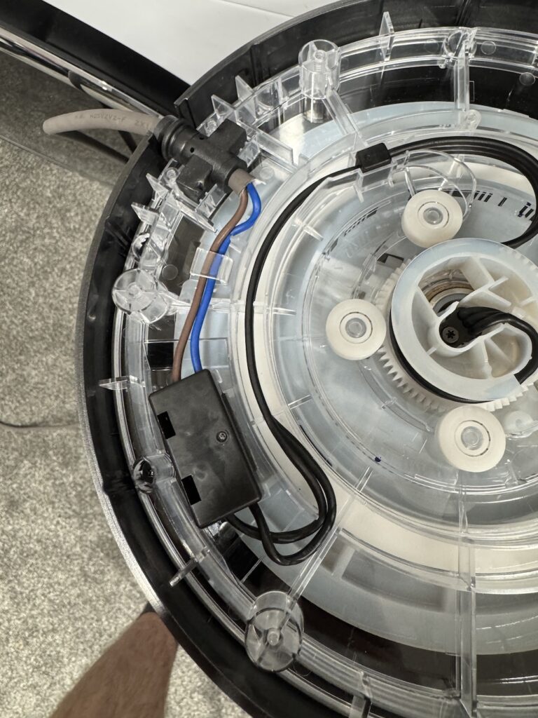
Add the main power cable wiring clip, secure the cable in place & do the same for the wiring that goes to the position sensor.
Clip in and ensure the wiring is in the guides
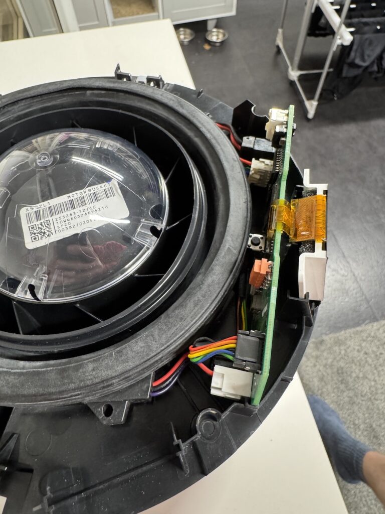
Add the lower PCB assembly, ensure you plug in the wiring connection at the back (I didn’t first time!)
It needs to be plugged in as placed into position.
Screw in the 3x securing screws.
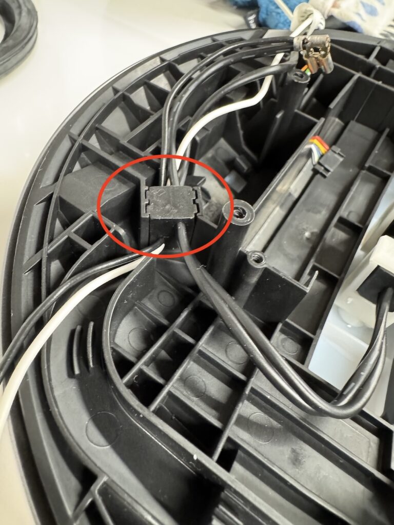
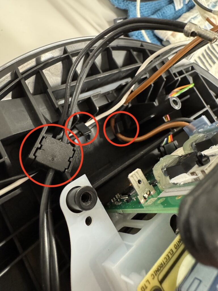
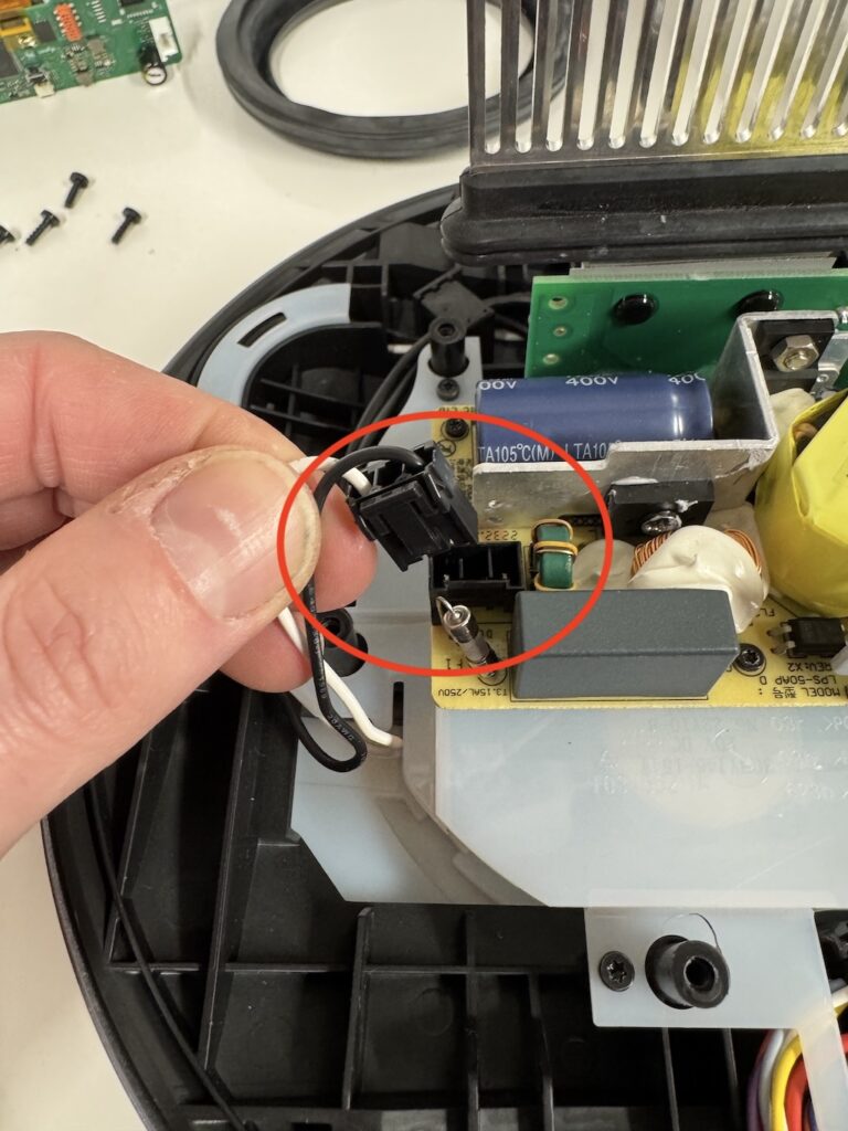
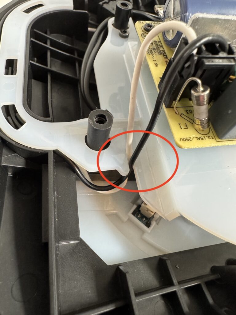
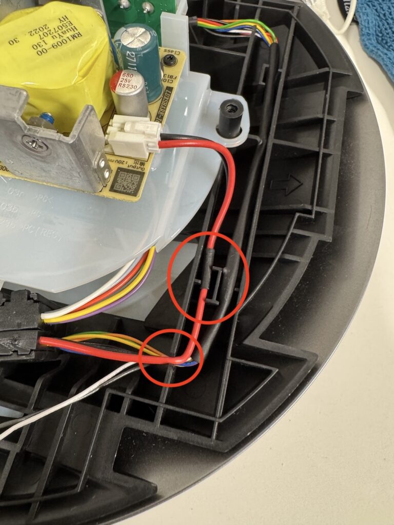
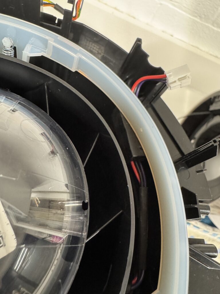
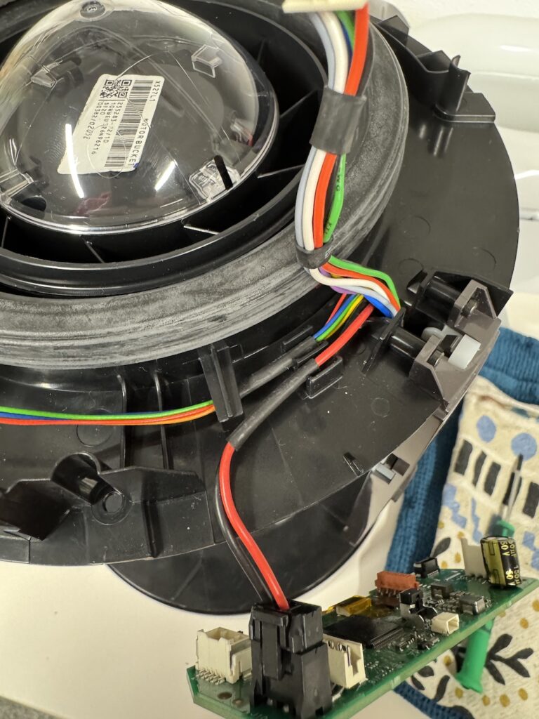
Secure the wiring. In the second picture, the black and white cable doesn’t route with the rest of the wiring.
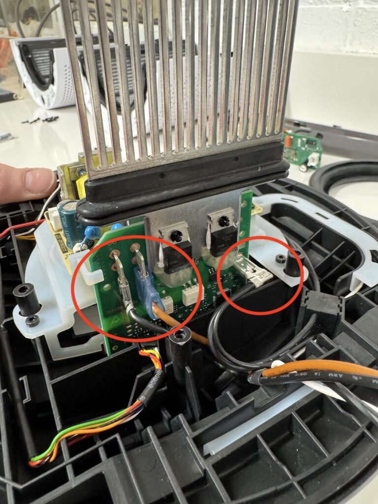
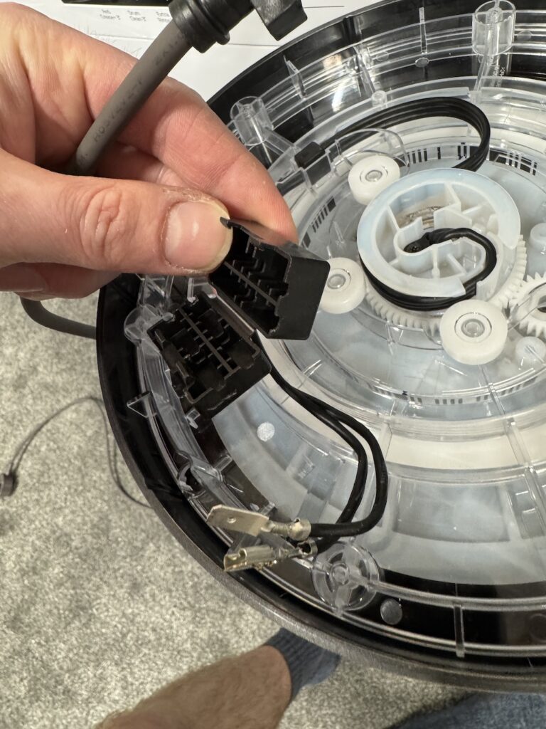
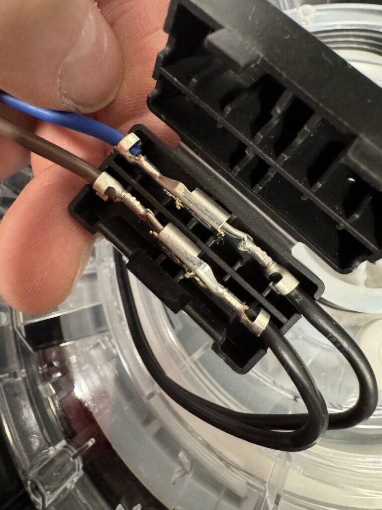
Connect the 3 wiring collections on the back. Ensure connected correctly as below.
Connect and clip in wires
Connect and guide in wires
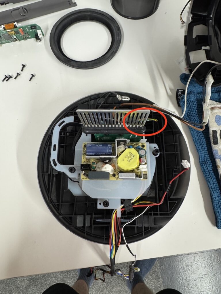
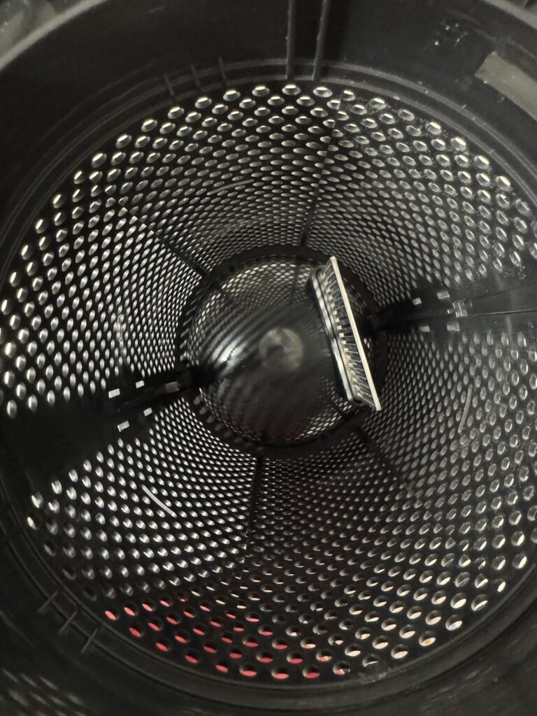
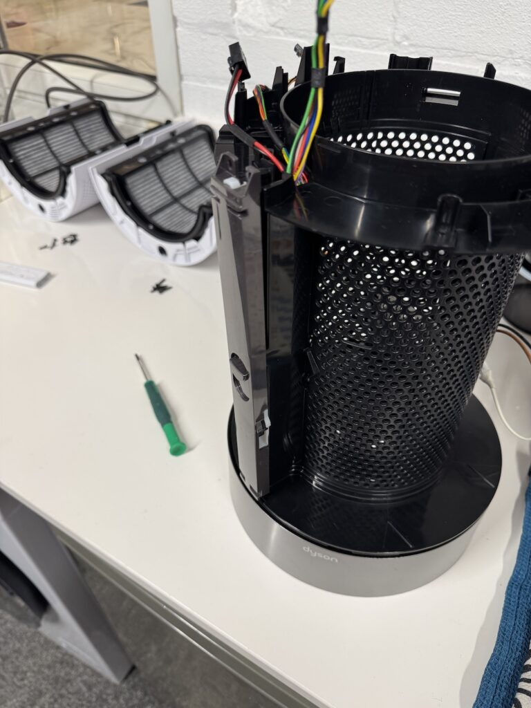
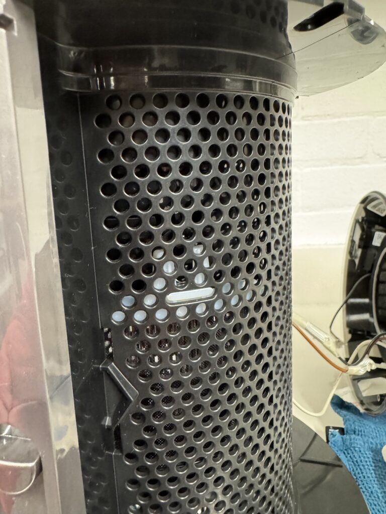
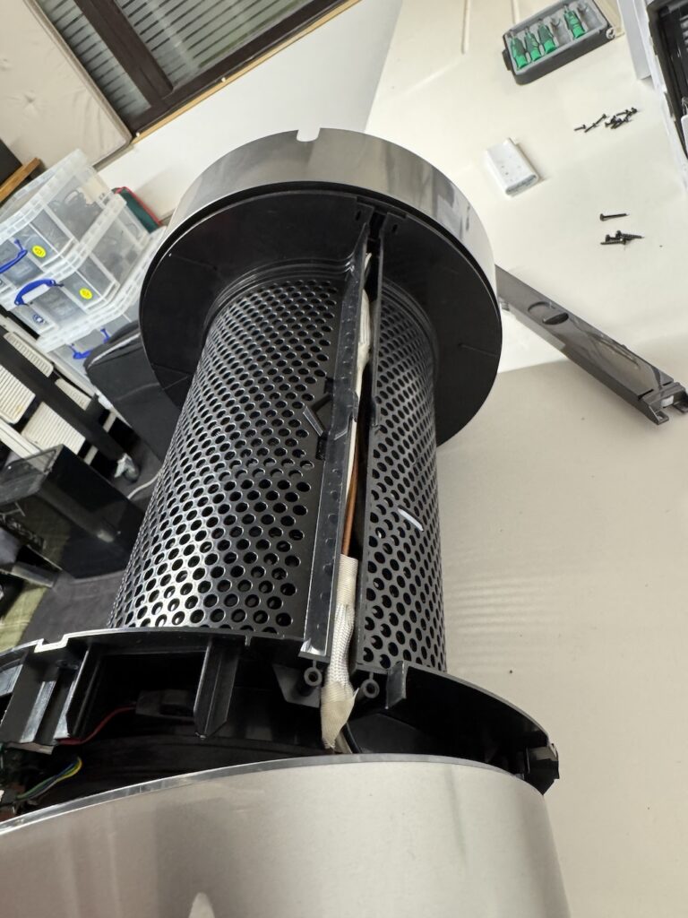
Place the filter housing onto the base assembly. It will only go one in one position as the heatsink for the PCB sits through it. It needs quite a bit of gentle force to get it on. (and off).
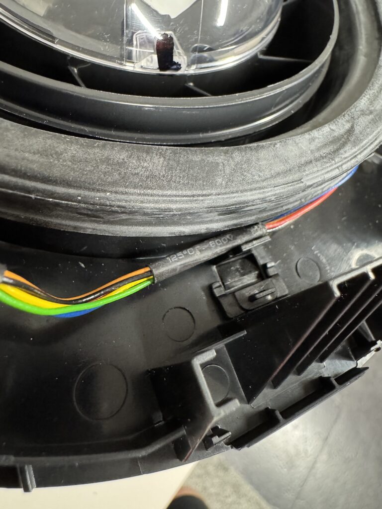
Ensure you guide the wiring up the side guides so it does not get caught between the base and filter housing.
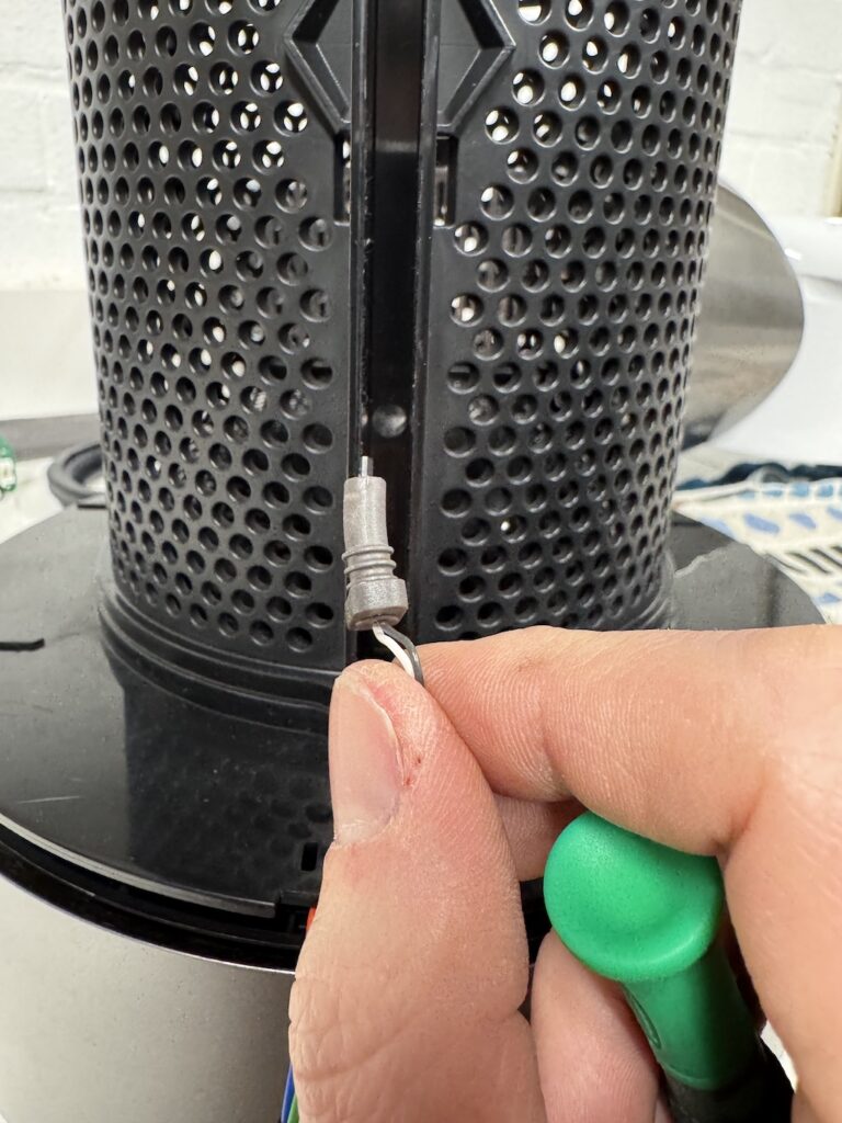
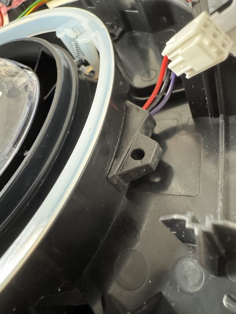
Push in this sensor into the filter housing. (Believe it to be a temp sensor). I used a small screwdriver tip. Don’t push on the wires, you need to push the rubber outer part to avoid damaging it. You can just about pull it through from the inside.
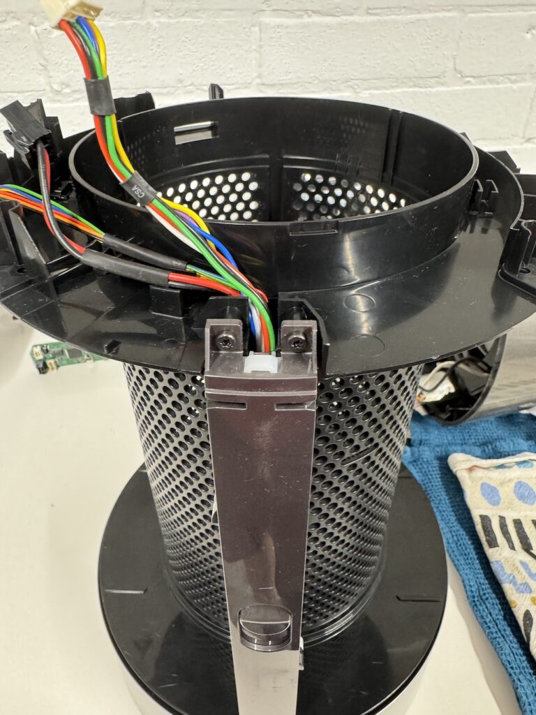
Route these wires up the side. Order them as the first picture. Then slide in the cover to position.
Screw in the 2x securing screws.
The side that has the wiring for the top part, keep aside for the moment
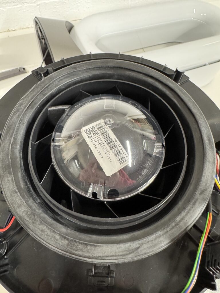
Insert the blower motor, noting the locking tabs position and also make sure it is orientated so that the power wire can go in its guide.
As it goes down it will all click into position and the wiring can be pushed into the guide. It can be quite a pain to get into position.
Add the seal making sure the lip is under the fan housing edge.
Route the wiring into its guides and add the control panel board / display
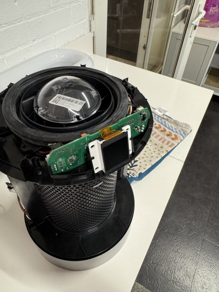
Plug in the wiring connectors. They are all different so cannot be mixed up.
Lastly, to add the top section / heater element, I found it easiest to lay it on its side, route the wiring up, add the wiring cover and screws.
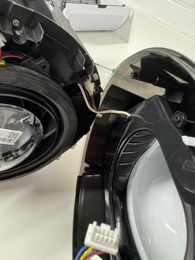
Next as you bring the two parts together, plug in the wiring that goes to the control board.
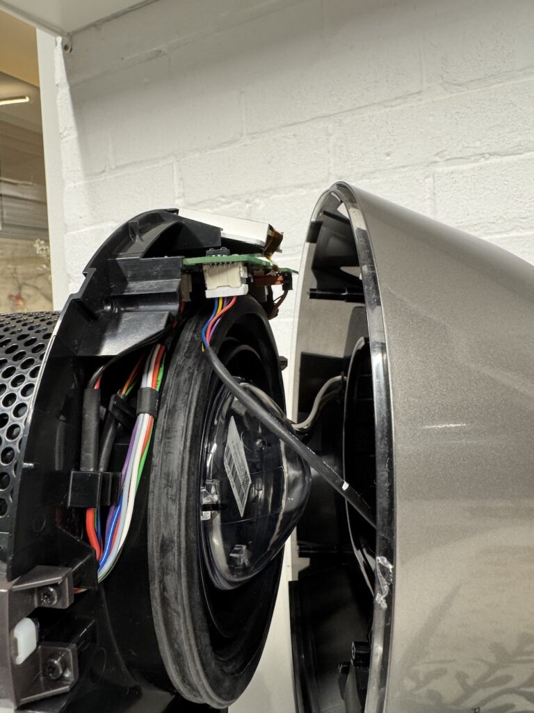
Then close the pieces together and add the 4 screws that are accessible from the filter area.
Now return back to the underside of the unit and add the main power wire back in. It’s not possible to get them round the wrong way due to the male / female spade terminal arrangement. Ensure all wiring is in its guides.
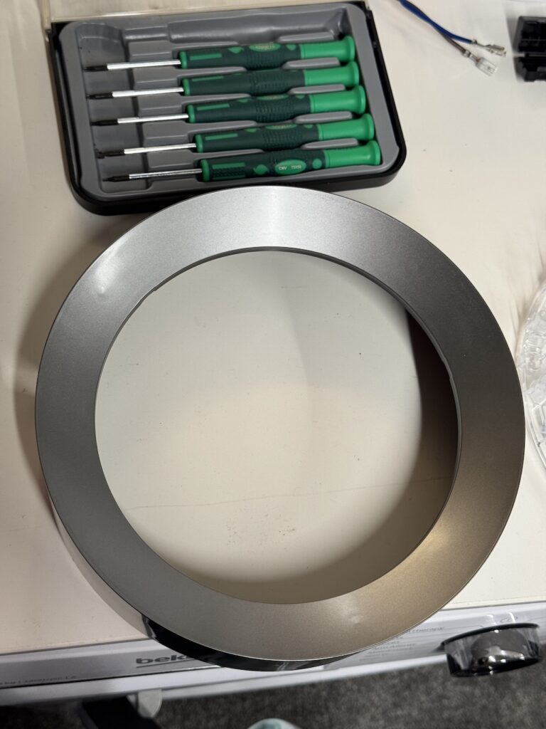
And finally add on the cover. With its many screws. Naturally, it will only go on in one position.
Lastly, clip in your filters.
Sit back and admire your work.
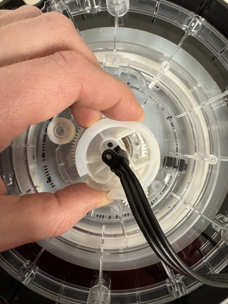
Note regarding rotation motor;
When I first re-assembled the fan the rotation was giving an error and it was making a clicking noise.
Turns out the during the fall it had popped itself open, presumably from the gears inside being force round. Then as it tried to rotate the internal gears skipped about.
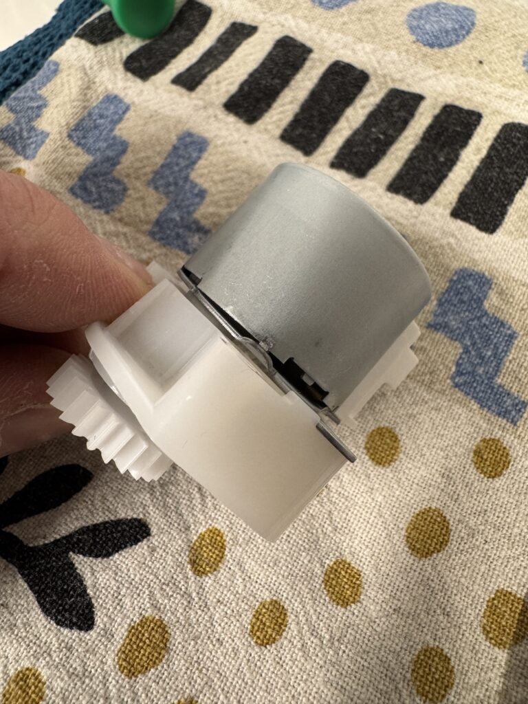
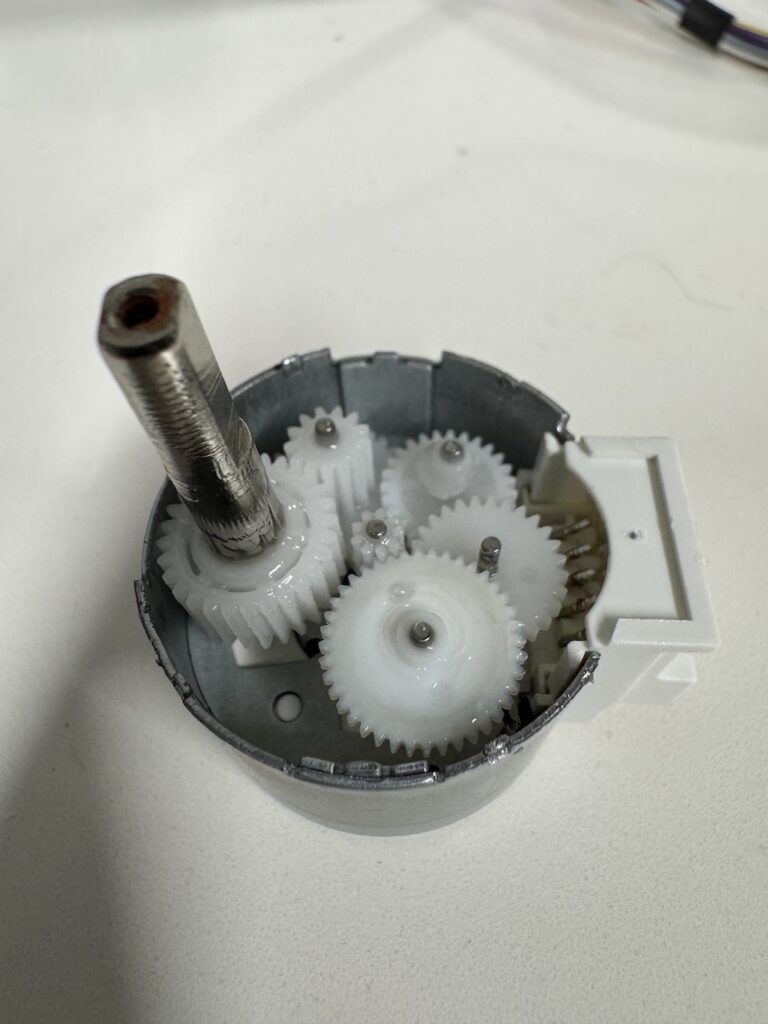
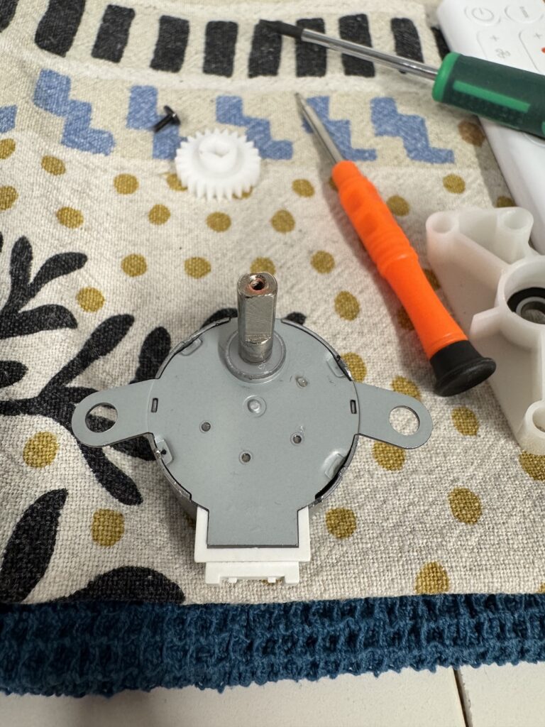
It was pretty simple to take the external cog off, one screw, then the plastic spacer / bearing pulled off. From here I was able to reseat everything and knock down the small tabs on the housing to lock it all together again.